Embedded Electronics HW/SW Engineer with expertise in Hardware & Software including PCB design and Analysis, firmware development and Android development apart from causual web-development (wordpress & Laravel) and to some extent photography.
After weeks of waiting, the parts I needed for a homemade Bluetooth speaker arrived. Pictured above are the PAM8403 amplifier board, Bluetooth module (USB powered with a 3.5mm audio jack), and a couple of 3-watt speakers. The power supply is a 5V 2A power supply I had laying around. All of the project materials amounts […]
Here I am sharing a header file called easyavr.h. This is a pretty basic header file with some helper functions related to input output pins of AVR
#ifndef __EASYAVR_H_
#define __EASYAVR_H_


//  Sets pin of port to 1
//
//  Example for PD2: PIN_ON(PORTD, 2)
#define PIN_ON(port,pin) ((port) |= (1 << (pin)))


//  Sets pin of port to 0
//
//  Example for PD2: PIN_OFF(PORTD, 2)
#define PIN_OFF(port,pin) ((port) &= ~(1 << (pin)))


//  Sets pin of port to value
//
//  Example for PD2: PIN_SET(PORTD, 2, 1)
#define PIN_SET(port,pin,val) (((val) > 0) ? PIN_ON((port),(pin)) : PIN_OFF((port),(pin)))

//  Sets all of port pins to OUTPUT mode
//
//  Example for PORTD: PORT_AS_OUTPUT(PORTD)
#define PORT_AS_OUTPUT(port) ((port) = 0xFF)

//  Sets all of port pins to INPUT mode
//
//  Example for PORTD: PORT_AS_INPUT(PORTD)
#define PORT_AS_INPUT(port) ((port) = 0x00)

//  Sets pin of port to OUTPUT mode
//
//  Example for PD1: PORT_AS_OUTPUT(DDRD, 1)
#define PIN_AS_OUTPUT(ddr,pin) ((ddr) |= (1 << (pin)))


//  Sets pin of port to INPUT mode
//
//  Example for PD1: PORT_AS_INPUT(DDRD, 1)
#define PIN_AS_INPUT(ddr,pin) ((ddr) &= ~(1 << (pin)))

//  Checks pin's value of port
//  Returns 1 or 0
//
//  Example for PD2: CHECK_PIN(PIND, 2)
#define CHECK_PIN(pinreg,pin) (((pinreg) & (1 << (pin))) != 0)


#endif
marcelclaro’s project for The Hackaday Prize aims to do just that. Instead of measuring blood directly, his project will measure blood glucose by shining light through a finger or an earlobe. Using light to detect blood glucose is something that has been studied in the lab, but so far, there aren’t any products on the market that use this technique.
There are two major problems marcel needs to overcome to turn this project into reality. The first is simply raw data for calibration. For [marcel], this is easy; he has Type 1 diabetes, and takes four glucose measurements a day. Patient heal thyself, or something.
The second problem is getting a photosensor that’s sensitive enough. By using an InGaAs PIN diode, a current-controlled oscillator, and a digital counter, [marcel] should have a sensor that’s good enough, with electronics that are cheap enough, to create some tech that is truly game changing for a few hundred million people around the world.
Arduino platform is a great tool for everyone who wants to play with microcontrollers in a simple and inexpensive way. It offers perhaps the quickest and easiest ways to do cool stuffs with its rich built-in library and easy to grasp interface. It’s also open-source and for this reason there are many open-source projects with it in the Internet. I have personally enjoyed it a lot. Although Arduino is pretty popular amongst many users, there is no good simulator software for it. Proteus VSM, on the other hand, is a very good circuit simulator software. However it lacks a model or simulator primitive for Arduino. Thus simulating Arduino in Proteus is in a way impossible. If these powerful tools can be synced together then a lot of new possibilities will arise. This is what I wondered from day one of Arduinoing. In this doc we will discuss how to integrate these software and simulate Arduino in Proteus.In Proteus we need to add a .hex or .coff file in a micro in order to simulate its behaviour. However Arduino works with .ino or .pde files and the folders that hold Arduino sketches don’t contain .hex or .coff files. Thus there’s no straight way. Now if there’s no straight path then we have to go around.Firstly we have to make a suitable Proteus schematic like the one shown. You can also download a template provided at the end of post.
Once the schematic is completed, we have to set the fuses and clock frequency as shown
[Shane] recently built an automated plant watering system for his home. We’ve seen several similar projects before, but none of them worked quite like this one. Shane’s system is not hooked into the house plumbing and it doesn’t use any off-the-shelf electronic valves. Instead, [Shane’s] build revolves around a device that looks like it was intended […]
Need to measure water quality and other parameters? DF Robot’s Analog pH Meter Kit is specially designed for simple interface and has convenient and practical connector and a bunch of features. Get pH measurements at ± 0.1pH (25 ℃). For most hobbyist this great accuracy range and it’s low cost makes this a great tool for biorobotics and other projects! It has an LED which works as the Power Indicator, a BNC connector and PH2.0 sensor interface. To use it, just connect the pH sensor with BND connector, and plug the PH2.0 interface into the analog input port of any micro-controller.
The Wiki page has a sample code for using this kit with arduino, along with schematic, specifications, features ,precautions and setup Instructions. The arduino Interfacing is simple and the schematic and code is available on the wiki page.
Interfacing with a pic is also straight forward, Shawon Shahryiar shared his project where he used a PIC16F684. Below is the demonstration video and code.
The simplest and easiest way to charge a battery with a solar panel is to connect the panel directly to the battery. Assuming the panel has a diode to prevent energy from flowing through it from the battery when there’s no sunlight. This is fairly common but not very efficient. [Debasish Dutta] has built a charge controller that addresses the inefficiencies of such a system though, and was able to implement maximum power point tracking using an Arduino.
Maximum power point tracking (MPPT) is a method that uses PWM and a special DC-DC converter to match the impedance of the solar panel to the battery. This means that more energy can be harvested from the panel than would otherwise be available. The circuit is placed in between the panel and the battery and regulates the output voltage of the panel so it matches the voltage on the battery more closely. [Debasish] reports that an efficiency gain of 30-40% can be made with this particular design.
This device has a few bells and whistles as well, including the ability to log data over WiFi, an LCD display to report the status of the panel, battery, and controller, and can charge USB devices. This would be a great addition to any solar installation, especially if you’ve built one into your truck.
Look around for heart rate sensors that interface easily to microcontrollers, and you’ll come up with a few projects that use LEDs and other microcontrollers to do the dirty work of filtering out pulses in a wash of light.
[Thomas] was working on a project that detects if water is flowing through a pipe with a few piezoelectric sensors. Out of curiosity, he taped the sensor to his finger, and to everyone’s surprise, the values his microcontroller were spitting out were an extremely noise-free version of his heart rate.
The piezo in question is a standard, off the shelf module, and adding this to a microcontroller is as easy as putting the piezo on an analog pin. From there, it’s just averaging measurements and extracting a heartbeat from the data.
This circuit is a Digital Temerature Sensor using a Dallas ‘1-wire’ DS18B20 Digital Thermometer
Firstly I would like to thank Pommie and Mike, K8LH from the Electro Tech Online Forum for their genourous help. This has been the most challenging project to date and they have helped immensely. They have tought me many valuable lessons about programming in Assembly language and it has really assitsted me in getting this project up and running.
Note: I would like to make a point that some snippets of their own code is used in this program. I have used it with their permission and please observe any copyrights or name recognition placed in the code. If you wish to use their snippets of code, please contact them via the Electro-Tech-Online forum.
How It Works
The DS18B20 is a direct-to-digital temperature sensor using Maxim’s exclusive 1-Wire bus protocol that implements bus communication using one control signal. In regards to hardware, this particular sensor is particularly easy to interface to. It only requires 1 external pull-up resistor to operate as opposed to an analogue sensor which possibly needs multiple external components such as resistors and op-amps.
In regards to software, opposed to analogue sensors, the Dallas 1-wire digital sensors are arguably as easy to interface to. While an analogue sensor will need an Analogue to Digital conversion using a voltage reference and possibly using an op-amp, the Dallas 1-wire direct to digital sensors require precise timing when it comes to communication. This program is fairly basic in principle as all it does is obtain temperature data from the DS18B20 sensor and display the temperature in Degrees Celsius on a 4 digit, 7 segment display. But when it comes to actually doing this, as you will see from the .ASM file, it is more complicated than it sounds. In words; the program first initialises the PIC16F628A Microcontroller. It assigns the Inputs and Outputs, zero’s all bank 0 RAM, initialises the display column select bit and configures TIMER 2. TIMER 2 is used to interrupt the normal loop of the program to update the 7 segment LED display.
After the Microcontroller has been setup, it begins communication with the DS18B20 Temperature Sensor. Communication routines take up just under half of the program memory. After the temperature has been gathered and stored in RAM, the Microcontroller takes the 12-bit signed/fraction integer and converts it into a decimal number then stores it in four general purpose registers in RAM.
For example, take the number D’95.8′. It is stored like this:
These registers are then used within the Interrupt Service Routine to call a table to obtain display data.
The program runs continuously, updating the temperature on the display just over once per 1 second.
Features Summary:
Temperature data gathered more than once per second.
TIMER 2 interrupt driven display.
Program expandable to include multiple sensors on the same 1-Wire bus.
Temperature range of -55.0 – 127.9 Degrees Celsius.
Please see the DS18B20 Datasheet for detailed information on the device.
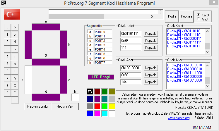
Yesterday I made a post regarding a seven segment display code generator, One of our reader Zafer shared his work with us through the comments section. Its a nice and useful utility. Its in Turkish language but its easy to use. Download it here from Dropbox.
Hi Muhammad
I follow your site with interest.
I’ve prepared the following program. hopefully be useful.
Zafer http://yadi.sk/d/0PqFkSf2P9gJr


 Once the schematic is completed, we have to set the fuses and clock frequency as shown


